|
MESH TIDYING
|
Right you've finished your mesh now comes the tidying
up! No matter how careful we are in constructing our mesh certain errors
always pop up during construction that are overlooked and might
cause problems later. I'm aiming to provide some general guidelines for
construction and some tips for tidying up - these tips are also extremely handy
when handling Conversion from other file formats. First I will deal with the Point Multiplication Problem. As
we all know Point numbers are a limiting factor of all the
earlier versions of LightWave - only now in Version 6 and above has it
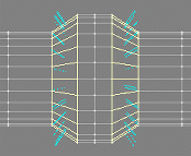
been done away with. A common problem I have seen people face is this one. They
have made a tube with various sections that are raised, they still want sharp
definition of the edges of these sections; but with a smoothing angle of 89.5
degrees (LightWave's default) which is usually used for tubes we get this
result:

|
|
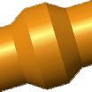
Now the most common technique I have seen used to eliminate this
problem it to cut out the offending section and then paste it back in again
like so
|
|
|
As you can see this does solve the problem - but what is the major
drawback with this technique? Well you have effectively doubled all the point
counts in these areas.
The result is that you will now have 192 points where there should
really only be 96! This might not be a problem on small meshes - but just
imagine what happens when you mesh has many antennas and gun barrels - it doesn't take a
genius to figure out that soon you will be in the realms of multi object ships that need to
be assembled in Layout! So.. The question is - how do we rectify this?
|
|
|
Well let's not cut and paste the offending object section out at all -
ensure that your tube has an absolute minimum of 24 sides - personally I always use
36 sides for everything but the smallest pipes and tubes that will never be that
noticeable. Poly's? Well LightWave can handle them - Points? - Start a new object!! Now
instead of cutting and pasting lets reduce the smoothing angle to just 60 degrees and
see what happens?
well - the smoothing error is still there
|
|
|
what about 40 degrees?
nope still there!
|
|
|
what about 30 degrees?
would you look at that - it's gone! BUT the tube now has a slight
faceted look to it - very subtle but there - check the highlight out and
compare to below - and that's because it is a 24 sided tube
|
|
|
let's use a 36 sided tube which will let us use a 40 degree
smoothing angle because of the greater number of sides:
So now you know why I always use smoothing at approximately 40
degrees and 36 sides for tubes - it saves on the points baby
|
|
|
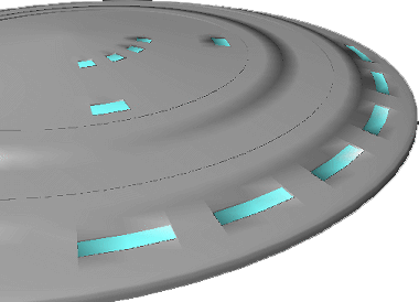
Next we move onto a related but dissimilar problem that many encounter - you
have Lathed an almost flat but yet curved surface - for example the top of a saucer
hull - and now you want to put raised panels and recessed windows in - lets look at
what it's like with a default smoothing angle of 89.5 degrees.
|
|
As you can see the smoothing errors on the raised panels and the windows are
awful - let's drop the smoothing down to 60 degrees and see what
happens.
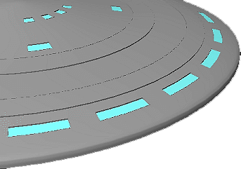
There it's gone - but sometimes you will encounter a mesh that will
still have smoothing errors at angles as low as 40, 30 or even 20
degrees! But remember though that you can set the smoothing on relatively flat surfaces to
just 10 degrees and make the saucer look smooth and thus eliminate smoothing on
any windows and raised edges. Remember that -- 10 degrees.
|
|
Now with that out of the way - which will help you out a lot in the long run
believe me....first we move onto tidying up the final construction. You can either
do these steps on the whole mesh if it is a relatively small one or section by section for
large complicated meshes.
First check that there are no points that are not connected to any
polygons
using the requester and checking in the appropriate box.
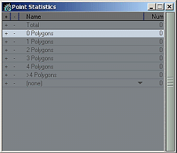
Select any and delete them.
|
|
Next Section by Section - or ideally Surface by Surface;
select the surface in question and then run the Points Merge Macro [to eliminate
the points problem as discussed before] followed by a Surface Smoothing Check as
discussed before - [this is something that you will commonly have to do when undergoing a
conversion.] Then run the Reduce Polygons macro, be careful with the reduce
polygons function as sometimes on a complex surface the result can be less than good and
polygon tearing will occur - and I've found more often than not the surfaces that
are lumpy and bumpy tend to not like this macro at all -- so be
careful with it -- if it doesn't turn out well then just undo and leave it as
is.
Reduce poly's works the best on objects that are either primitives or
are derived from primitives - again this is the reason why I don't just run it on a
whole object in one go --- rather surface by surface individually.
|
|
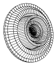
Another extremely good reason for polygon reduction is this setup - which
occurs when you have lathed something, and I'm sure you have come across it or will one
day

|
|
it looks like this in wire frame
|
|
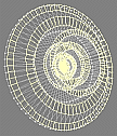
now all these polygons do not really have to be there as they are all
perfectly flat in relation to their neighbor's - i.e. they are coplanar
|
|
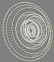
after running the reduce poly plug-in we get this result with 567 less
polygons
|
|
the mesh looks no different rendered

but layout has 567 less polygons to worry about!
|
Now sometimes with reduce poly functions, point merge, point weld - and
other functions you will be left with poly's that consist of either one or two vertices -
these are for all intents and purposes useless and should be selected and then cut away -
they do have their uses such as hair with a medium or large polygon line size in layout
for instance; but in the general scheme of things just get rid of the little things!

|
|
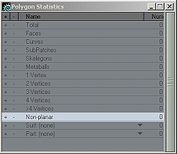
Next select the non planar polygons - these are basically poly's that are
curved and always have more than 3 points - they can and sometimes do cause rendering errors
in layout as they tend to give the rendering engine a little headache. Select them - there
may be many - so deal with areas one at a time.
|
|
Now the simplest way to get rid of a non planar poly is to
triple it
|
|
|
leaving this result - all well and done!
|
|
|
- but sometimes it can leave you with loads of little triangular
polygons - especially around multi point windows
|
|
|
The trick here is to select polygons wisely and run the merge
polygon macro then check for non planar again - if any - triple and
repeat - you'll end up with a nice poly layout in the problem area with no
non-planar polygons.
|
|
|
An important thing to bear in mind is that Layout can cope with
non-planar quite happily sometimes - so check in a render and animation first to see which
are the real problem areas and then rectify just them if necessary.
|
|
Last thing to do now is to check that there are no polygons that
coexist exactly in the same place - these are a nightmare for the
render engine - do it by simply pressing the unify button - this tool will find
the offending polygons and delete them. - easy eh?
There is another check and that is for alignment - but you should
always attempt to only ever use double sided polygon surfaces where they are absolutely
necessary and ensure your vertices face the correct way.
Sometimes conversions can have ridiculous polygon facing setups and even then
the Align polygons function won't have much effect on them - so that check is really up to
you in the end.
I hope this helps you all out
Above all - Have fun!!
|
|
Need help detailing your spaceships? Have to make a
cityscape fast? Need to fill any area with random believable
detail?
The
Ultimate Greeble & Nurnie Collections will make light work of any of your Projects! Check them out now!

|